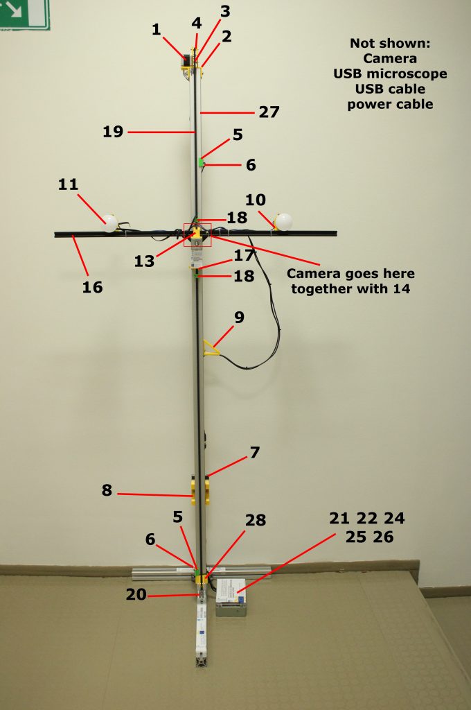
- Use 3D printer to print all the plastic parts. PLA and 0.4 mm nozzle are good enough:
- Motor and pulley support (part #2)
- Belt Clamp Front, Belt Clamp Back (print 2x sets, part #18)
- Belt Guide Bottom (part #28)
- Belt Loop Top (part #13)
- Belt Loop Bottom (part #17)
- Cable Support (part #9)
- Camera Screw Ring (not shown)
- Light Holder (print 2x, part #10)
- Switch Support (part #5)
- Weight Guide (part #8)
- (ZIP archive of all parts in STL format)
- Cut a 40×40 mm (1.5×1.5 inch) aluminum strut profile into 4 pieces: 43 cm (part A) , 60 cm (part B), 174 cm (part C) and 10 cm (part D). Assemble parts A and B into a T-shape using two corner brackets (part #26) and corresponding T-Slot Sliding Nuts and bolts.
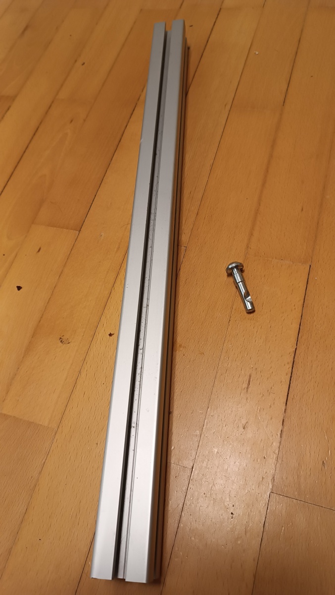
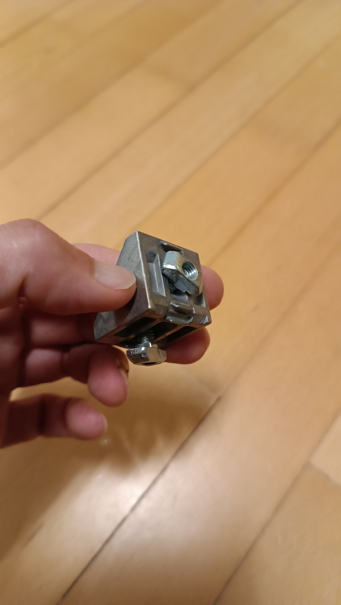
- Drill a 8mm diameter hole in the part C 60 mm from the end. This is the hole for the belt. (Don’t mind the yellow and green parts that are visible in the image – they will be mounted later on.)
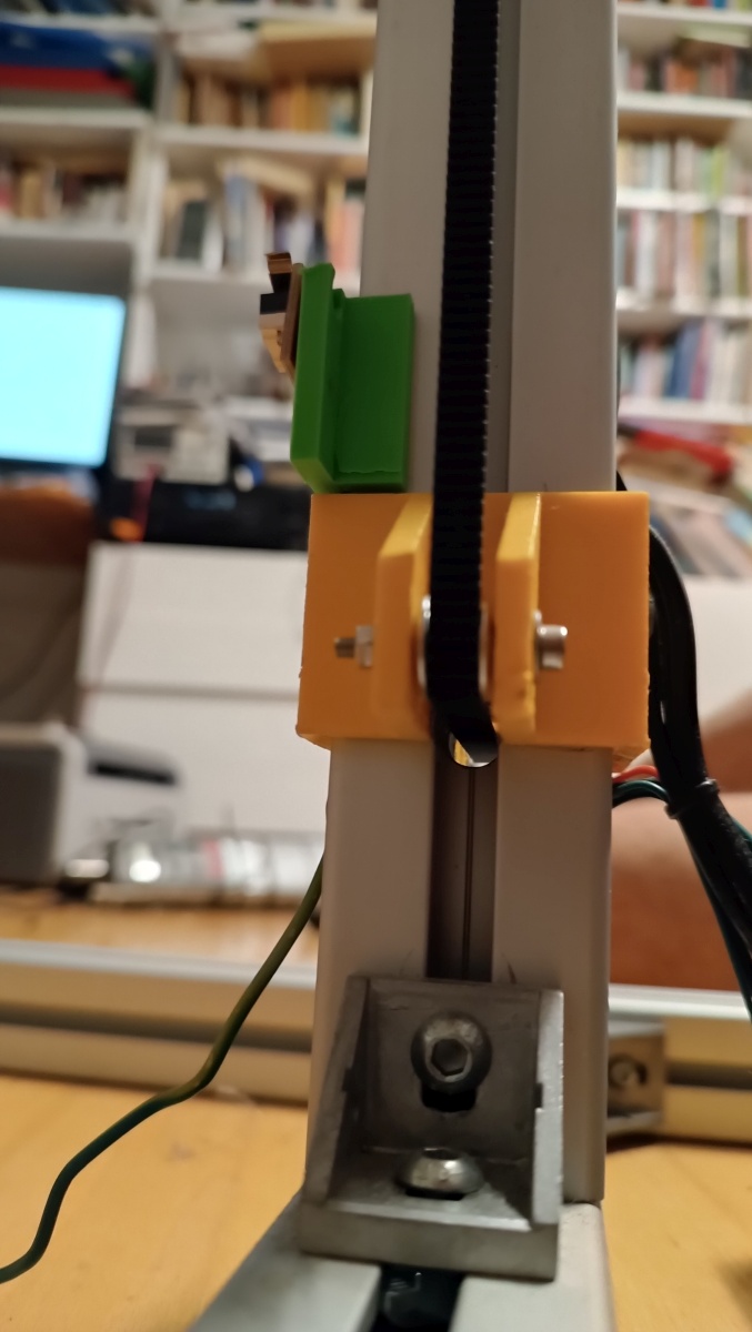
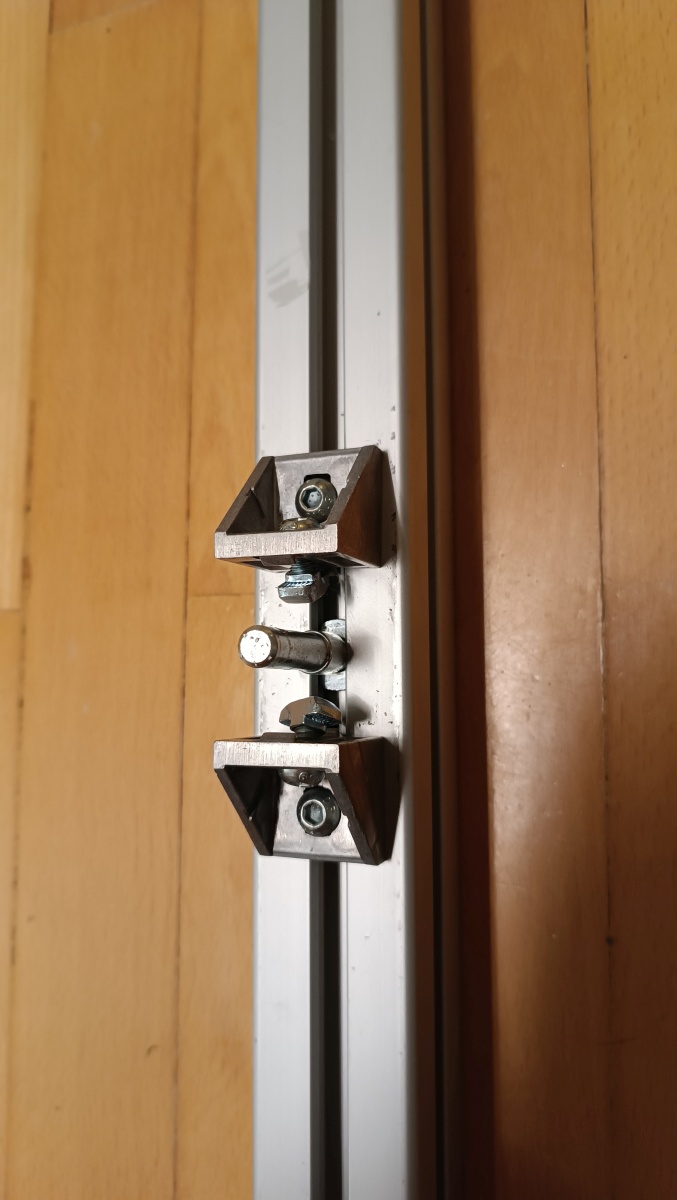
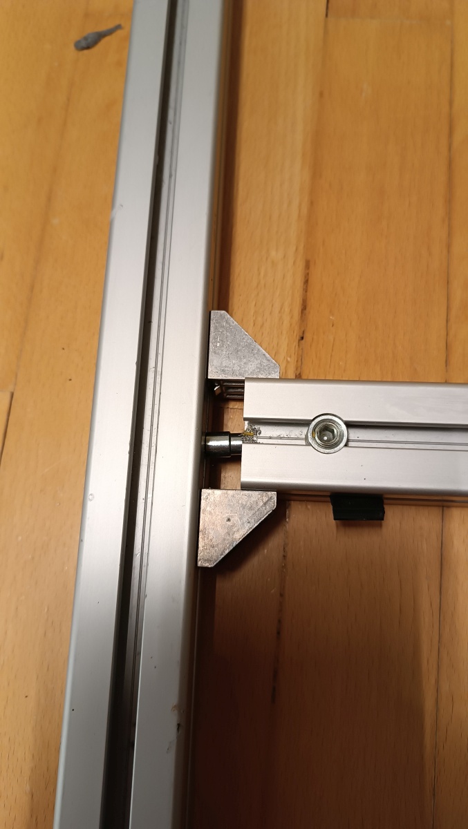
- Connect the part C vertically to the part B using two corner brackets (part #26).
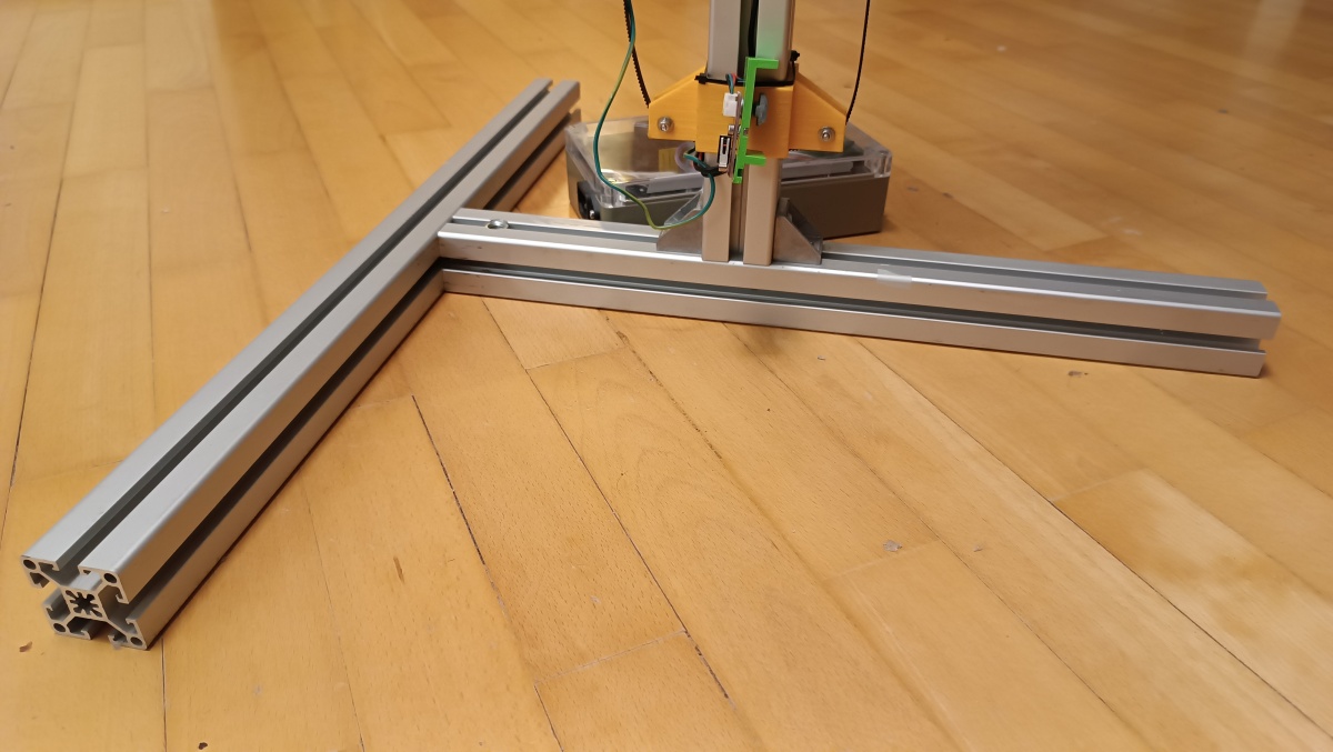
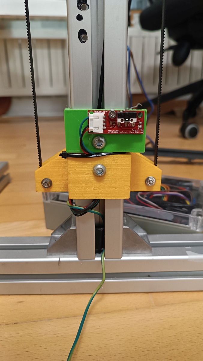
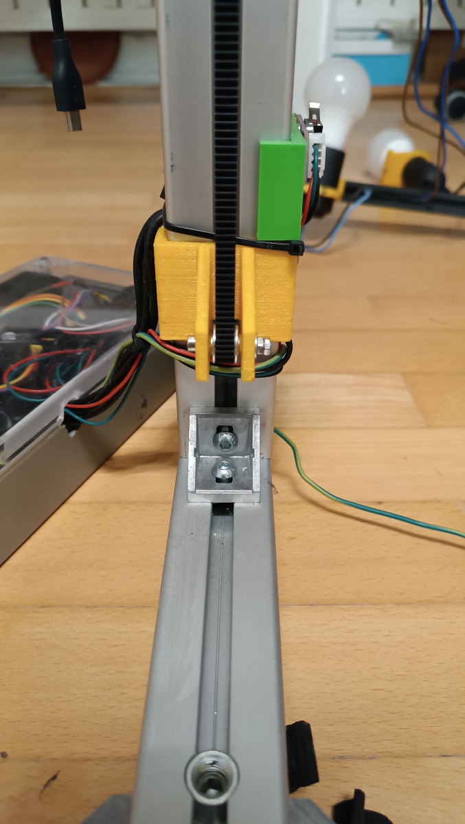
(as already said, ignore the parts that are mounted on the vertical profile in the image) - Mount the Belt Guide Bottom (part #28, yellow thing in the image) on the bottom part of the vertical aluminum profile, just above the corner brackets. Use two T-Slot sliding nuts and bolts to mount it from both sides (front, as shown in the image below, and the one on the opposite side).
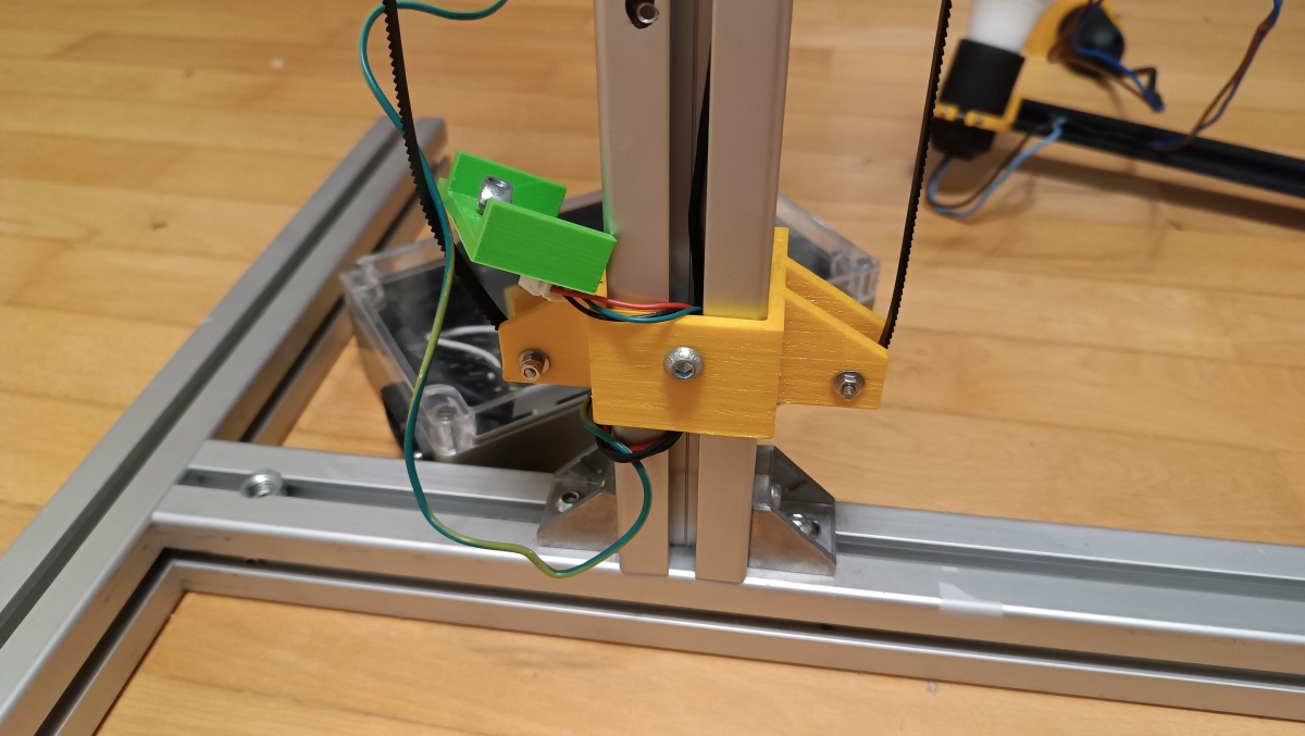
- Mount the limiting switch on the Switch support (part #5, green thing in the image) directly above the Belt guide bottom (part #28).
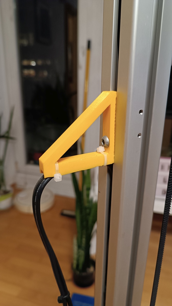
- Mount the cable support (part #9) at the side of the vertical bar.
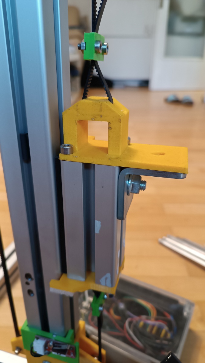
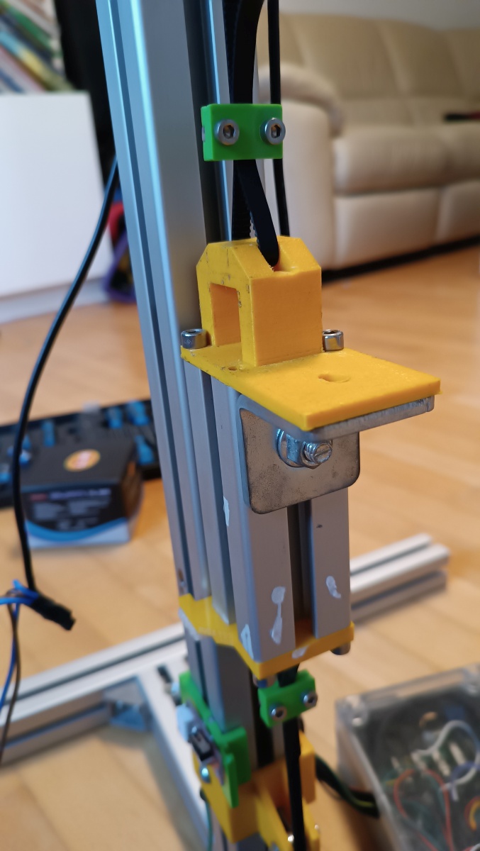
- Assemble the slider that will carry camera and lights. Take part D (10 cm long 40×40 mm aluminum extrusion) and insert a 10 cm long sliding element 10/10N into the profile. Screw the 3D printed part Belt Loop top (part #13) on one side and Belt Loop bottom (part #17) to the other side. Add a L-shaped bracket for additional strength.
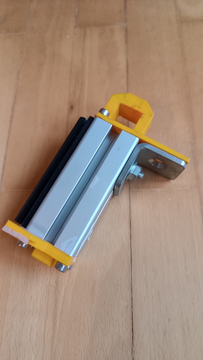
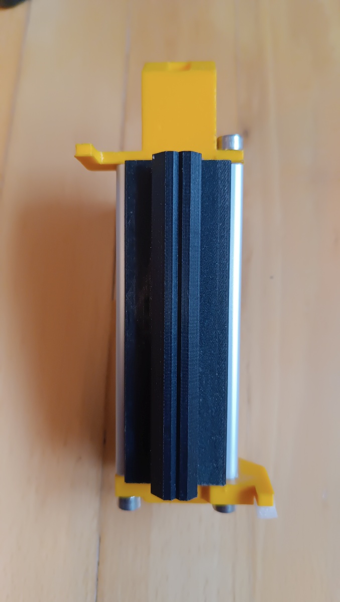
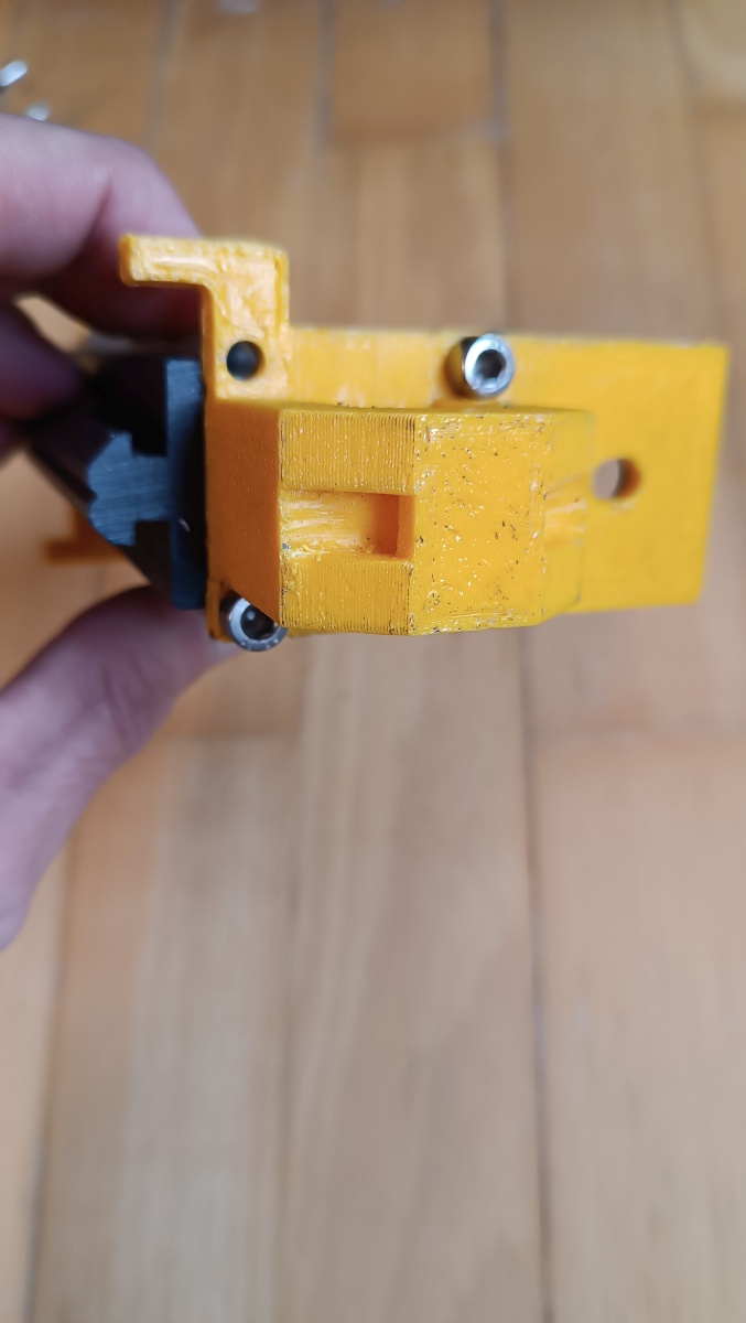
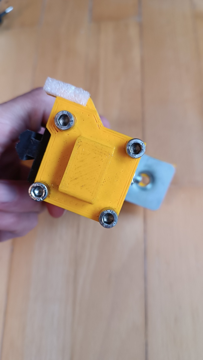
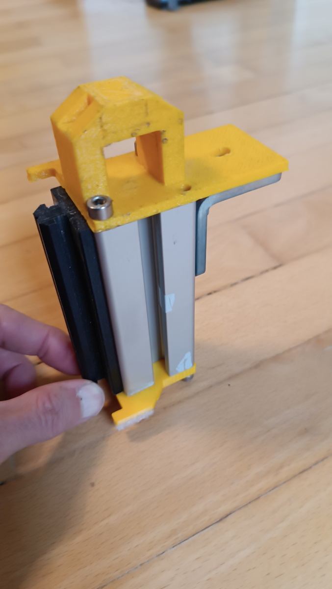
- Insert the assembled slider into the slot of part C.
- Assemble motor and pully on 3D printed part #2.
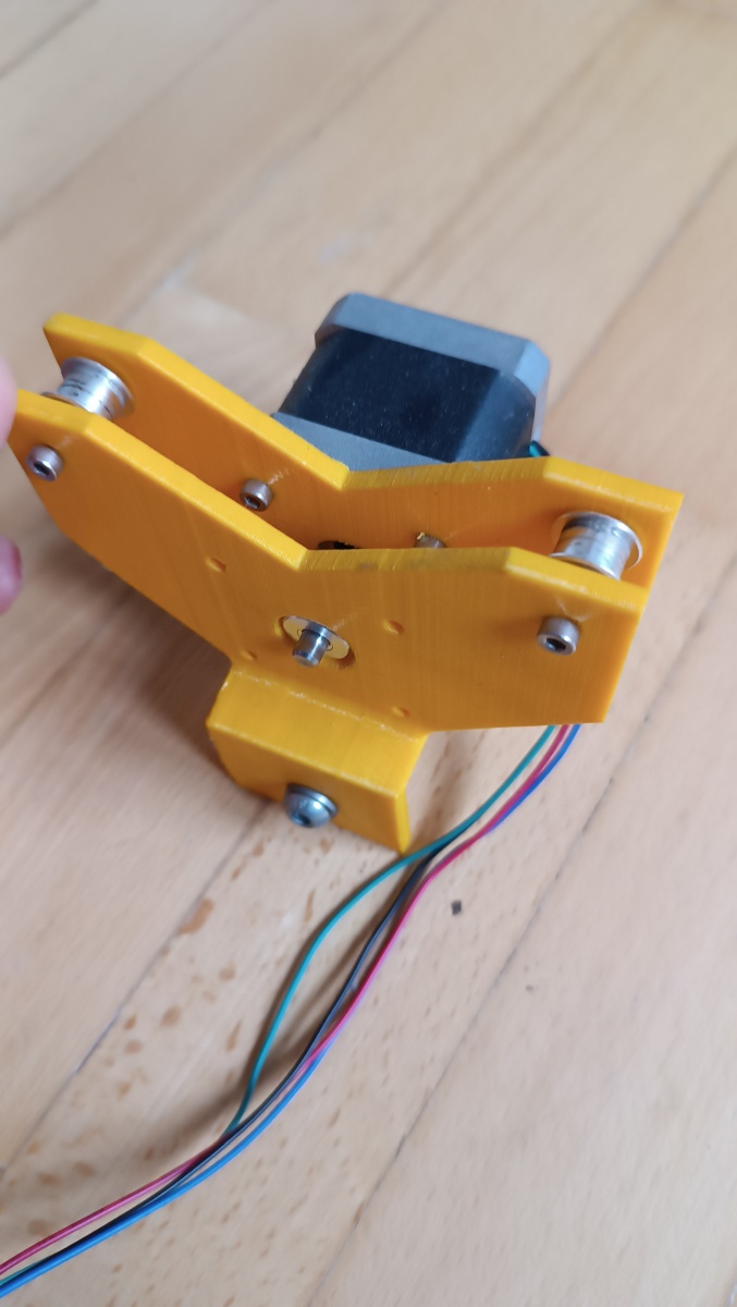
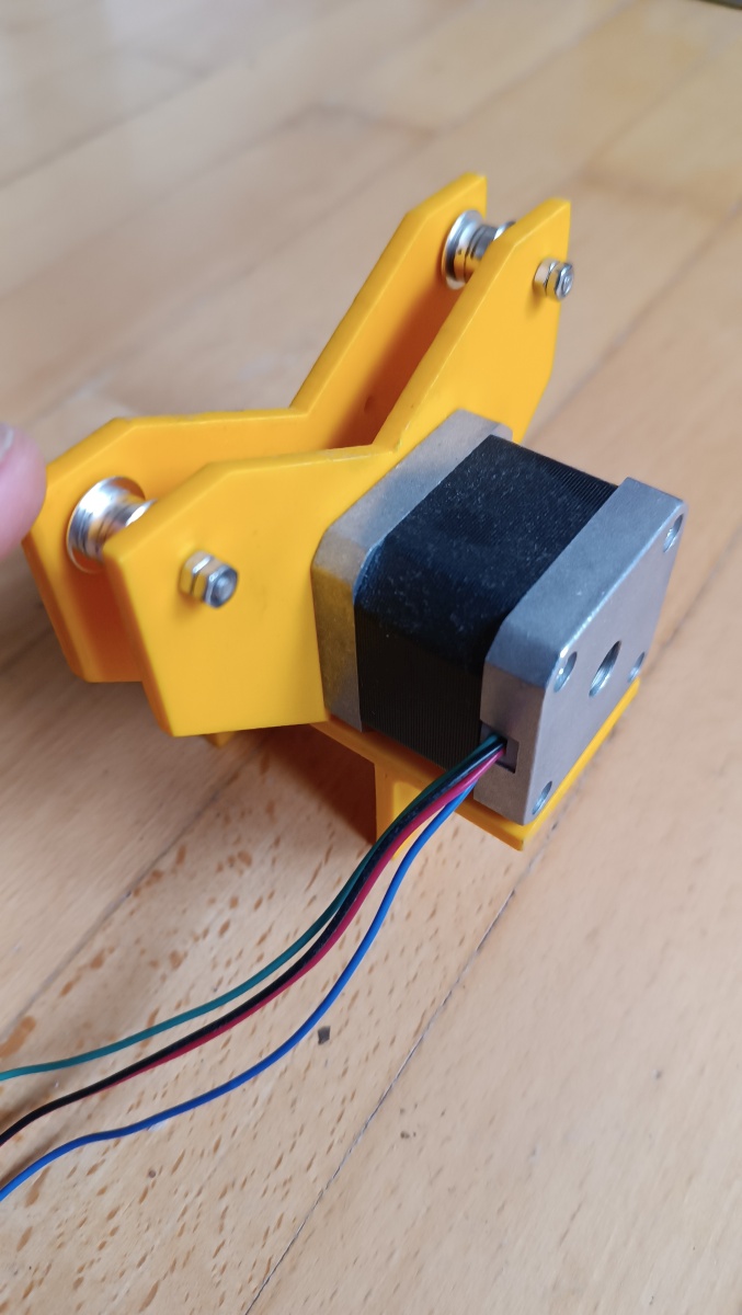
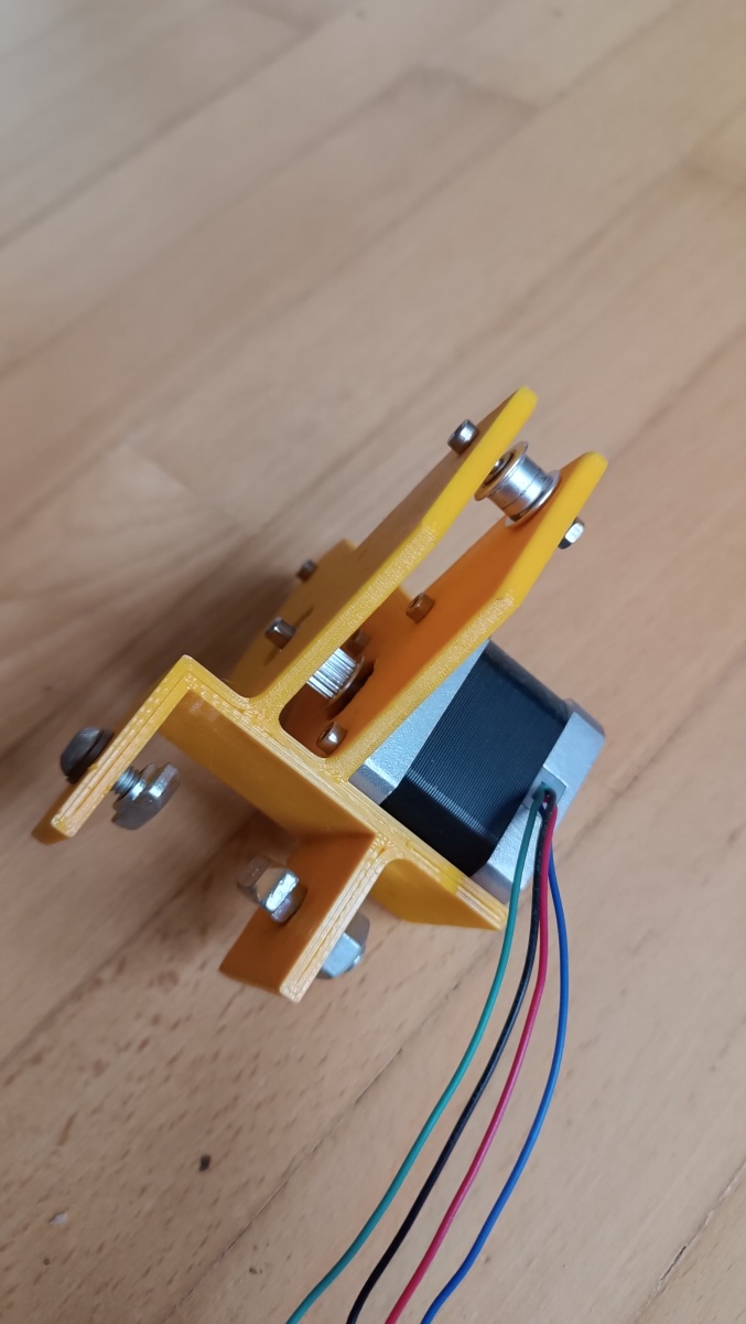
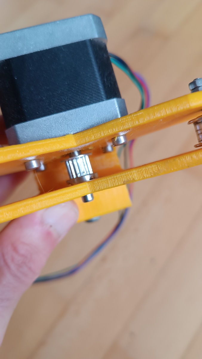
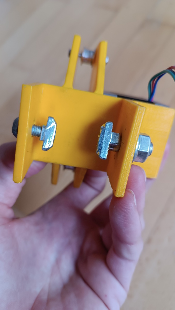
- Fix part #2 on the top of the part C using two screws and T-slot nuts.
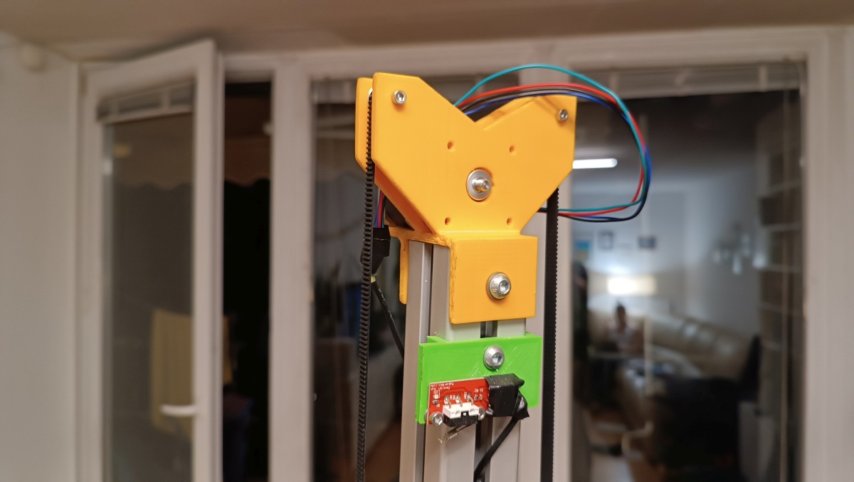
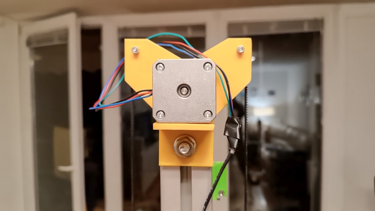
The list of components we used is accessible here. We hope it serves as a guide for anyone wishing to construct their own dermoscope stand or simply as a starting point for future projects.
